Configurable Many-core Accelerator for Embedded Systems:
On early embedded systems, accelerators were placed on a separate chip next to the main processor, or on an independent board connected to the main system. Nowadays, it is common to find systems where a general purpose processors (e.g. ARM and ATOM) and several accelerators are integrated on the same chip (e.g. XILINX ZYNQ). The high level of complexity of these circuits has been reflected on their non-recurring engineering and manufacturing cost. As a consequence, many-core embedded systems are mainly mass-produced in the form Application Specific Integrated Circuits (ASICs) for covering the needs of large markets. Two negative effects are derived from this. first is, medium and small size companies which cannot afford manufacturing their own chips are unable to provide customized solutions even if they possess the necessary know-how. This leads to non-optimal implementations based on the chips available on the market. Second and most important, is the lack of many-core architectures for highly specialized markets. The design space exploration for these systems is hampered by low production volumes since they do not justify the costs of developing an ASIC. One possible alternative for fulfilling this gap is the utilization of field-programmable Gate Arrays (FPGAs). In [1][2][3], we have developed a Configurable Many-core Accelerator (CoMA) for FPGA-based embedded systems. Its architecture comprises an array of processing and I/O-specialized cores interconnected by a Network-on-Chip (NoC) [4]. The I/O cores provide the connectivity with other system components through the industry-standard Advanced eXtensible Interface (AXI) bus. In a typical design flow, an application is partitioned and the most compute-demanding tasks are executed on the accelerator. With the proposed approach, the details of task synchronization and I/O access of the accelerator are hidden by an abstraction layer. Task partitioning is left to the designer, thus allowing more flexibility during application development than with automatized partitioning. The high level view of the system leverages the customization of the accelerator on an application basis. This way, CoMA promotes the development of many-core solutions for highly specialized applications.
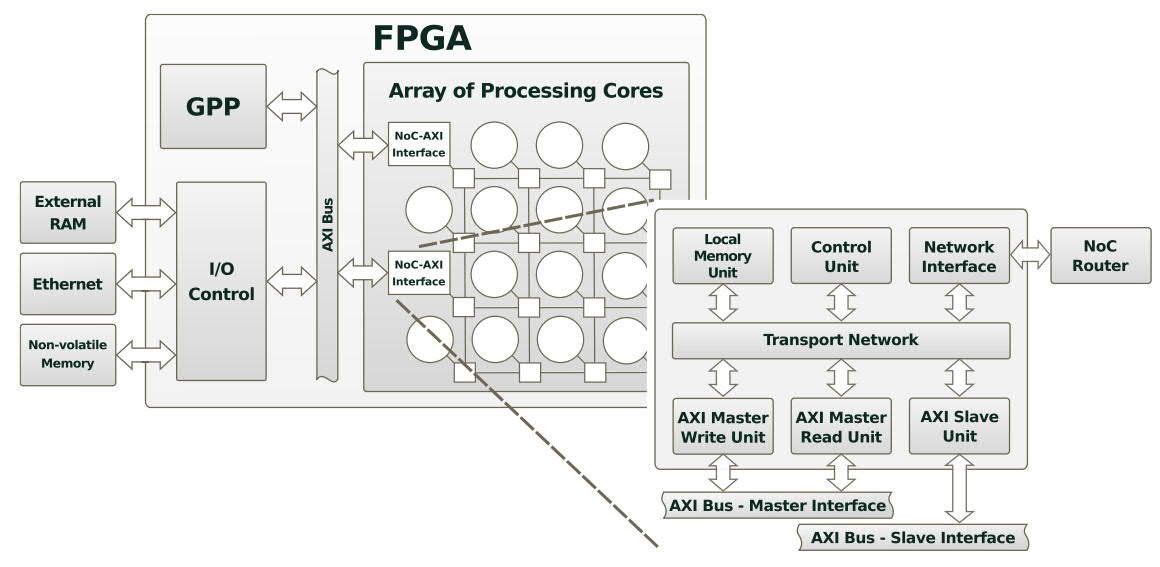
Fig. 1. CoMA Architecture.
The architecture combines an array of processing cores interconnected by an NoC, with an I/O interface based on the AXI protocol. CoMA provides the designer
with a system abstraction layer that facilitates task partitioning and peripheral access. The implementation of the I/O interface was verified through simulation, and synthesized for an FPGA.
The key features of CoMA are as following:
- CoMA explores the concept of utilizing an array of processing cores for accelerating the execution of the compute demanding tasks of an application.
- Comprises an array of processing and I/O-specialized cores interconnected with NoC (Fig. 1).
- Connectivity with other system components is provided through the industry-standard AXI-bus thus assuring compatibility with third-party IP cores.
- Massage passing communication model that facilitates the implementation of data-flow applications and maximizes task parallelism.
- A system abstract layer that provides transparent inter-task communication and access to I/O devices (Fig. 2).
- External RAM and I/O peripherals are mapped onto a single memory address space.
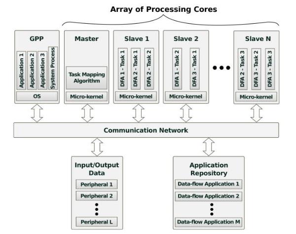
Fig. 2. CoMA Architecture.
CoMA is designed to accelerate data-flow applications, which are typically represented as task graphs. Each application comprises a set of tasks (nodes) that pass messages among them (edges). The System Abstract Layer defines a very simple application programming interface (API) through which the tasks of an application can exchange messages and get access to the I/O devices. The developer only needs to create a file for each task and use the API to implement all the communication functionality of the task. Fig. 3 shows an example of a small application, while Fig. 4 depicts the typical work flow.
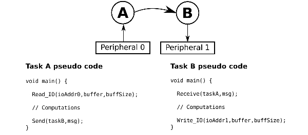
Fig. 3. Block diagram of the prototyped network.
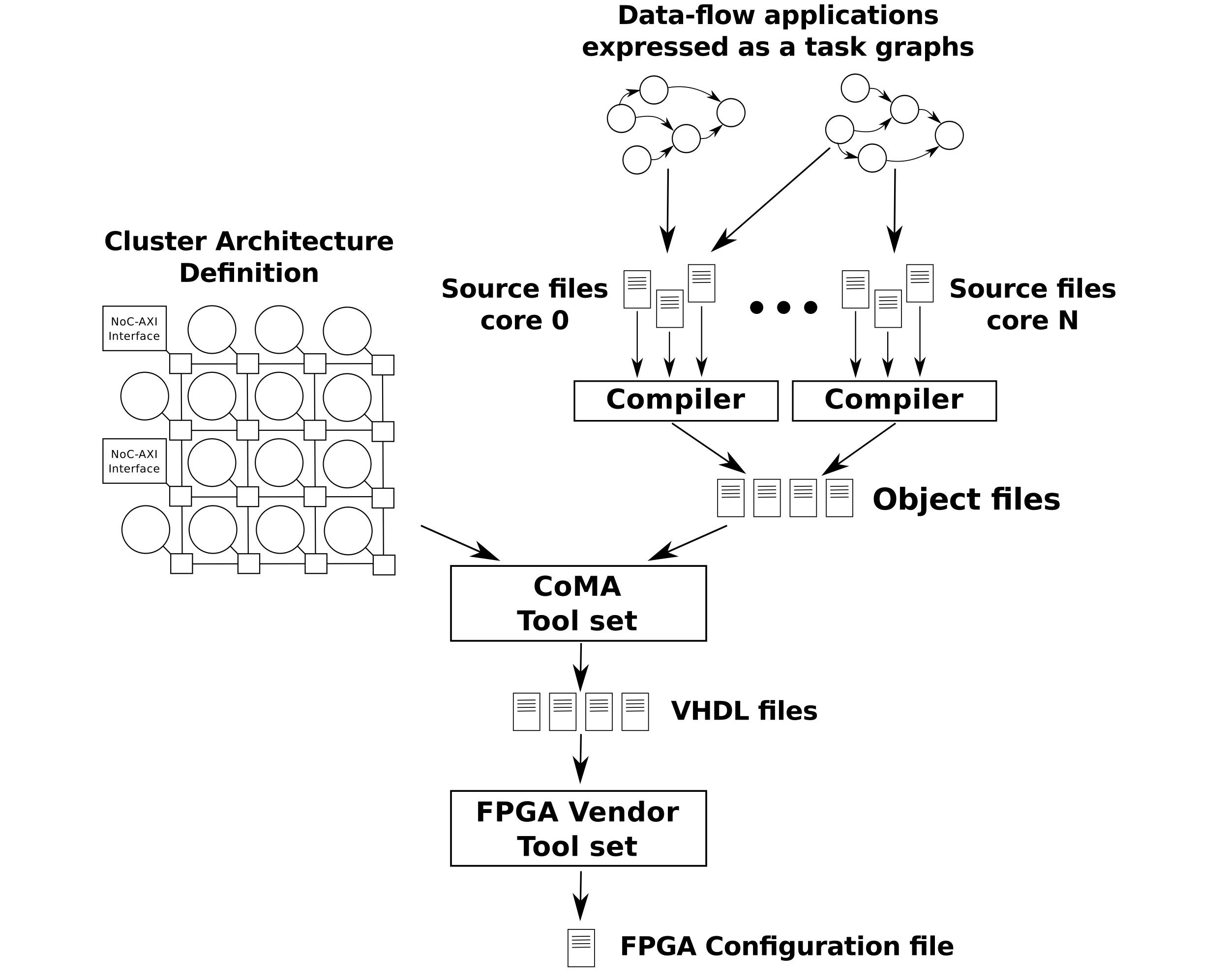
Fig. 4. Typical work flow for CoMA-based systems.
System Overview:
The platform is connecting MIPS based “plasma” processors together through network interfaces [1]-[6]. Each node in the network contains a plasma processor, a local memory, a DMA controller, and our Tra-NI network interface [6]. Tra-NI is used to reduce kernels’ networking overhead, and to highlight the mapping impact. The system is managed by a central manager (CM) located on the node (0,0). CM serves the user requests for application execution. It maps the requested application, allocates tasks of the application to the mapped nodes, collects task termination acknowledgements, and keeps track of available nodes. Each application is known by its number (appID), and when it is mapped for execution it gets a unique invocation number (invID). Thus, multiple copies of an application can be run simultaneously without any interference on each other. CM retrieves application information and their binary code from the application repository. Application repository is generated using our developer software. System applications can be developed using standard C, while inter-task communications are handled by specific primitive functions. The software converts applications to the proper binary code by means of the MIPS compiler and HeMPS tools, and constructs the applications task graph by traversing their source code; while the user is allowed to modify them. The proper repository format is generated using extracted binary codes and task graphs. The overall scenario for execution of an application can be summarized as follows. First, CM receives the execution request for an application from the user, and assigns a unique invID to it. Then, CM loads the task graph of the application from the repository, and maps it onto NoC nodes according to the applied mapping algorithm. Subsequently, CM allocates application’s tasks to the associated nodes, and updates the system current state. When a node receives an allocation request, its kernel stores the binary code into the local memory, and passes the processor control to the task. Finally, the kernel acknowledges CM when the execution of the task is finished on the allocated node. Notice that, the current state of the system –stored in CM– is updated after allocation and termination of each application. Also, the maximum number of applications that could be injected per second into the system is denoted as full. In all set of experiments, the user requests are sent to CM through UART modules, and CM reports back to the user on the mapping result and applications execution. At the end of each experiment, CM reports the elapsed cycles of different steps (mapping, allocating, and execution) for each application.
FPGA Prototyping:
In order to evaluate the functionality and time complexity of CoNA, as can be seen from Fig. 5 and Fig. 6, a 5x5 instantiation of the network is prototyped on a Xilinx ML605 evaluation board featuring a Virtex-6 XC6VLX240T FPGA [5][6]. The frequency chosen to operate the system is 100 MHz. A differential signal obtained from an onboard 200 MHz oscillator is internally handled by a Digital Clock Manager (DCM) module to produce the desired clock signal which is fed to the network through a BUFG component in order to minimize skew. Each set of experiments is executed for 20 seconds, and the NoC developer software generates random sequence of requests on behalf of the user. The application repository and the PEs' local memories are implemented using internal RAM blocks. The Xilinx data2mem application is used to update the contents of these blocks directly into the FPGA's configuration file by using a BMM file which provides a description of the RAM blocks arrangement and several MEM files which describe the content of the memories.
Hypervisor and embedded Operating System for resource management:
FPGA-based many-core embedded systems are likely to have tens or hundreds of resources connected together. Such systems will feature an extremely dynamic workload where an unpredictable sequence of different applications enter and leave the system at run-time. In order to handle the featured dynamic nature, a run-time system manager (hypervisor) is required to efficiently map an incoming application onto the system resources. Applications are modeled as a set of communicating tasks, and the mapping function of the central manager (CM) of the system decides on the appropriate node for each task. The job of the CM, called application mapping, is to allocate application’s tasks onto the system resources efficiently in terms of network latency and power consumption. Besides efficiency, the mapping algorithm needs to be light in order to react quickly to different run-time requests and events. We proposed efficient algorithms for run-time application mapping problem, aiming at minimizing both congestion probability and power consumption [5][7].
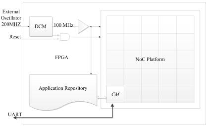
Fig. 5. Typical work flow for CoMA-based systems.
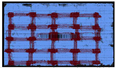
Fig. 6. 5x5 prototyped system layout. Network routers and links: brown color, network nodes and other components: blue color.
References:
- [1] M. Ramirez, M. Daneshtalab, P. Liljeberg and J. Plosila, "Towards a Configurable Many-core Accelerator for FPGA-based Embedded Systems," in Proceedings of 8th IEEE 8th International Symposium on Reconfigurable Communication-centric Systems-on-Chip (ReCoSoC), pp. 1-4, July 2013, Germany.
- [2] M. Ramirez, M. Daneshtalab, P. Liljeberg, J. Plosila, “NoC-AXI Interface for FPGA-based MPSoC Platforms,” in Proceedings of 22nd IEEE International Conference on field Programmable Logic and Applications (FPL), Norway, Sept 2012.
- [3] G. Georgakarakos, M. Daneshtalab, and J, Plosila, “Efficient Application Mapping in Resource Limited Homogeneous NoC-based Manycore Systems,” in Proceedings of 8th IEEE 11th International High Performance Computing & Simulation (HPCS), pp. 207-212, July 2013, finland.
- [4] M. Daneshtalab, M. Ebrahimi, P. Liljeberg, J. Plosila, and H. Tenhunen, “Memory-Efficient On-Chip Network with Adaptive Interfaces,” IEEE Transaction on Computer-Aided Design of Integrated Circuits and Systems (IEEE-TCAD), Vol. 31, No. 1, pp. 146-159, Jan 2012.
- [5] M. Fattah, M. Ramirez, M. Daneshtalab, P. Liljeberg, and J. Plosila, “CoNA: Dynamic Application Mapping for Congestion Reduction in Many-Core Systems,” in Proceedings of 30th IEEE International Conference on Computer Design (ICCD), pp. 364-370, Sept 2012, Canada. (26% acceptance rate)
- [6] M. Fattah, M. Daneshtalab, P. Liljeberg, and J. Plosila, “Transport Layer Aware Design of Network Interface in Many-Core Systems,” in 7th International Symposium on Reconfigurable Communication-centric Systems-on-Chip (ReCoSoC), 2012.
- [7] 90. M. Fattah, M. Daneshtalab, P. Liljeberg, and J. Plosila, “Smart Hill Climbing for Agile Dynamic Mapping in Many-Core Systems,” in Proceedings of 50th ACM/IEEE International Design Automation Conference (DAC), pp. 1-6, June 2013, USA. (24% acceptance rate)
Back to main page
|